.png)
| Item | Value |
|---|---|
| Measured gases | LEL flammable gas |
| Measuring range | |
| Detection principle | catalytic combustion |
| Accuracy | |
| Resolution | |
| Response time | |
| Ingress protection | |
| Explosion protection | |
| Operating temperature | |
| Power supply | |
| Output signal |
HTTM20 gas transmitter is a high-end transmitter independently developed by our company, which is widely used in petrochemical, fire protection, environmental protection, scientific research, etc. in indoor and outdoor leakage hazardous places. It can monitor the concentration of gas at the explosion-proof site for a long time, monitor the leakage, and display the gas concentration digitally; When the leaked gas concentration reaches the set value, the alarm control system sends out an audible and visual alarm signal to prompt the duty personnel to take safety measures, and at the same time, the transmitter provides the switching output (capacity of 220V, 2A), and automatically opens the safety device (such as exhaust fan, solenoid valve) to avoid the occurrence of dangerous accidents and ensure the safety of life and property.
Executive Standards:
& GB12358-2006 "General Technical Requirements for Environmental Gas Detection and Alarm Instruments in the Workplace" & GB3836.1-2000 "Electrical Equipment for Explosive Gas Environments Part 1: General Requirements" & GB3836.4-2000 "Electrical Equipment for Explosive Gas Environments Part 4: Intrinsically Safe "I"" &GB50493-2009 Design Code for Flammable Gas and Toxic Gas Detection and Alarm for Petrochemical Industry &GB16808-2009 Technical Requirements and Test Methods for Flammable Gas Alarm Controller
1.1 Features:
●HTTM20 gas transmitter output mode: 4-20mA, RS485 output, switching output optional
●The shell is explosion-proof and can be used in hazardous environments
●4-digit LCD display (with backlight), function indicator
●Good long-term stability and small zero drift
● Good repeatability and high reliability
●Equipped with infrared remote control, there is no need to open the lid to achieve calibration operations on site
|
Note |
|
The transmitter is a bus system, which needs to be transmitted with the adapted controller, and the optional controller: such as AT-8A, AT-99A, etc |
|
Field |
Indicators |
|
Detect gases |
flammable gas |
|
Detection principle |
electrochemical principle |
|
Service life |
3 years (typical) |
|
Measurement range |
0-100%LEL |
|
Operating voltage |
DC12-30V, typical DC24 |
|
Sampling method |
Diffusion |
|
Precision |
±10%FS |
|
Power consumption |
Less than 2W (DC24V) |
|
Warm-up time |
≤ 60 seconds |
|
Response time |
≤ 60 seconds |
|
Transmission distance |
Less than 1000m |
|
Transmission method |
Shielded cables |
|
Installation method: |
Wall type, tube mounting |
|
Operating temperature |
-10℃~60℃ |
|
Relative humidity |
0-95% RH (non-condensing) |
|
Explosion protection |
ExdⅡCT6 |

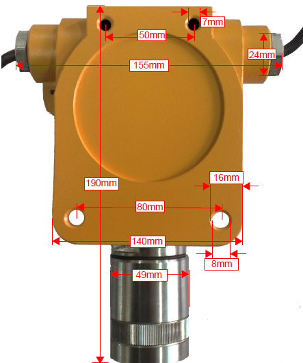
Main Material:Cast aluminum ruler Dimensions:190mmх155mmх90mm
Heavy Quantity:Approx. 2Kg Explosion protection:IP66Ingress protection
AL:Alarm indicator light at the first alarm pointAH:The second alarm point alarm indicator
Power supply:Transmitter Normal Operation Indicator Communications/Breakdowns:Communication status indicator
Fix with #8 screws for installation, refer to the specific installation method (4. Transmitter installation)。

HTTM20 gas transmitter is an explosion-proof product that can be installed in chemical production workshops and other places where there may be gas leakage under measurement.
|
Note |
|
The transmitter is a diffusion sampling method and is installed in a position where the target gas can be detected as much as possible. |
The following principles should be followed during the installation process:
1. It must comply with the "Electrical Safety Regulations of the People's Republic of China for Explosive Hazardous Places" and the GB50493-2009 "Petrochemical Flammable Gas and Toxic Gas Detection and Alarm Design Code".
2. When it is necessary to wire from the shell, the inlet joint must be tightened after completion.
3. Note that the transmitter must be facing down when installing the transmitter, otherwise it may affect the transmitter due to external media.
4. The transmitter must not be sprayed or painted. If the spray painting work is carried out at the place where the transmitter is installed, it must be ensured that the transmitter flameproof sheet is not glued to the paint. The paint will prevent the gas to be monitored from spreading into the sensor, affecting the detection results.
5. The transmitter should try to avoid working in a serious water vapor environment or directly exposed to rain and lightning.
6. The transmitter selection point should be selected near the valve, pipeline interface, air outlet and other leak-prone places, as close as possible, but do not affect the operation of other equipment, and try to avoid high temperature and high humidity environments, and avoid external influences, such as splashing water, oil and the possibility of mechanical damage. At the same time, it should be considered to facilitate subsequent maintenance and calibration.
|
Note |
|
1: The installation method of transmitter can be wall-mounted and tube-mounted, which should ensure that the installation is firm and reliable. 2: The transmitter should be fixed facing down when installed, and after the correct connection, the transmitter cover should be completely covered to meet the explosion-proof requirements. Mounting the sensor facing up may damage the transmitter by immersion in water or other liquids. |
2, installation method
A:Wall Mounted
Connect the mounting bracket with the transmitter with ф6×30mm bolts; Fix 2 ф6~ф8mm expansion bolts on the wall, the spacing position is shown in the installation size, and add flat pads, elastic pads, nuts and screw them in turn.
B:Tube mounted
Attach and fix the transmitter to the tube (horizontal or vertical pipe). Note: When installing the transmitter, the contact between the sensor and the gas must be made downward.
3, installation steps
(1) First, thread the transmitter on-site wire (note that the wire should be introduced into the transmitter for wiring);
(2) Secondly, refer to the transmitter wiring diagram to connect correctly;
(3) Thirdly, according to the installation method adopted, refer to the installation diagram, and install the transmitter on the base plate first;
(4) Finally, refer to the corresponding installation diagram to install the base plate on the wall or pipe.
|
Note |
|
The connection line interface of the transmitter must be insulated |
Be sure to cut off the power supply when connecting the wires, and the power supply voltage of the transmitter must not exceed the limit (30VDC)。
ATTM20 gas transmitter transmits signals (IN, GND, +24V, TX, RX) with the control host through shielded cables, and selects shielded wires according to the output signal, with a three-wire system for the output 4~20mA signal and a four-wire system for the output RS485 signal.
|
Note |
|
The transmitter terminal block allows a maximum wire diameter of 7.5 mm |
Transmitter's power supply, communication, display, signal processing, switching output and other functions of wiring diagram 4, see the functions of each terminal block in detail《Table 1: Transmitter terminal block function》。
The normal operation of the transmitter and the realization of each function are premised on the correct wiring, so be sure to ensure that all cables are connected correctly before the transmitter is powered on.Generally, we have equipped you with shielding schematic wires at the factory, and defined the cable function according to the cable color。
Red cable: Connect +24V
Black cable: connect to the negative electrode or power supply ground
Blue cable: signal end
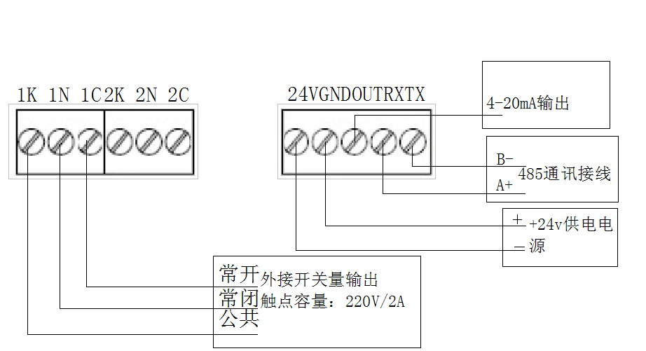
Table 1: Transmitter terminal block function
|
Logo |
Function |
Logo |
Function |
Logo |
Function |
|
24V |
24V power supply positive |
OUT |
4-20mA signal output |
GND |
24V power supply negative |
|
TX |
485 Communication Positive (A) |
RX |
485 Communication Positive (B) |
|
|
|
1K |
The first set of relays is always open |
1C |
The first set of relays is at the common end |
1N |
The first set of relays is normally closed |
|
2K |
The second set of relays is always open |
2C |
The second set of relays is at the common end |
2N |
The second set of relays is normally closed |
Switching output wiring instructions:
At the factory, we connect a set of switching output by default, of which the red wire switch is always open, the black wire switch is usually closed, and the blue wire is connected to the common end.
If there are calibration conditions on site, regular calibration can be carried out according to the following instructions; If you do not meet the conditions, you can go to the relevant measurement department or our company for calibration.
Calibration is carried out on schedule, with a period of 3-6 months to ensure the measurement accuracy of the transmitter. If there is often a high concentration of the measured gas in the use environment, the calibration period can be appropriately shortened; Otherwise, the calibration period can be appropriately extended.
• Confirm that there is no gas to be tested in the environment;
• Carefully check whether the power supply and output contact terminals of the transmitter are wired correctly;
• Check whether the power supply voltage is normal;
• Open the top cover of the transmitter and check whether the power supply voltage between GND and 24V in the terminal block is normal.
• Check whether the remote control used for infrared remote control calibration is working properly;
• Plug in the power of the transmitter and wait for a period of time for the transmitter to work stably.
After making sure that there is no gas to be tested on site, press the "SET" button of the remote control to display "109" on the LCD screen, use the "UP" key and "DOWN" key to adjust "109" to "888", and press the "SET" key again to display. 1", then press "SET", and press the "SET" button to exit after the LCD screen displays the number stable. Make the alarm controller or transmitter LCD display show "0.0".
At the same time, you can also use the one-click zeroing function: press and hold the "ZERO" key on the remote control for three seconds, and release the "ZERO" key after the "CLR-" prompt appears on the LCD screen to complete the zero point calibration.
You can use the remote control "SET" key to enter "666" to view the calibration point value, or set the calibration point value. Configure the gas equivalent to the concentration value of the calibration point, use the remote control to adjust the password value "888", and adjust the current display value to "2" to determine the calibration point calibration. The gas that has been configured to continue until the current display number has not changed significantly, press the "SET" button of the remote control, adjust the current number "2" to "0", and press the "SET" button again to exit the calibration state.
Our bus transmitter adopts RS485 communication, we have set the communication address as "1" by default when leaving the factory, you can use the remote control "SET" key to enter the password "123" to view the communication address value, or set the communication address value. Use the remote control to adjust the password value to "123", adjust the current display value "1" to the address value you need, and press the "SET" button again to exit the setting state.
Before the product leaves the factory, our company has calibrated and strictly inspected the product as required, and we promise that the product complies with the relevant national and industry standards and regulations.
For users who purchase our products, our company will be responsible for repair or replacement free of charge within one year from the date of purchase; However, the following situations are not covered by the free warranty:
1. Negligence, accident, disaster, improper use and installation;
2. Unauthorized disassembly and modification of the product;
3. Damage caused by the transportation process;
4. Problems in materials, design or manufacturing that cannot be found at the scientific and technological level of the product when it leaves the factory.
The quality assurance of the product is based on the following circumstances: the user's purchase has determined the suitability of the product; All products have been carefully inspected during the user's purchase process, and no defects have been found; The user has been trained or certified not to replace any part of this product without authorization, and to maintain and maintain the product in strict accordance with the instructions in the text description materials of this manual.
However, any problems caused by the repair or maintenance of instruments by unqualified personnel, or the use of uncertified consumables and parts, are not within the scope of this product's warranty commitment.
If a product does not comply with the quality warranty of this manual, the user may use the sole remedy and our sole liability, first by replacing or repairing the non-quality guaranteed product, and then refunding the original price of the product.
We shall not be liable under any circumstances for any other special, incidental or consequential damages, including loss of profits or benefits, arising out of the sale, manufacture or irregular use of the products sold, whether such statement appears in contract or in civil clauses, including express liability in civil clauses.
Users should acknowledge that the product itself determines the purpose and suitability of your purchase. We are not responsible for any technology or other advice or services provided to users regarding the use of our products. Therefore, we are under no obligation or responsibility to advise or assume the consequences.
We reserve the right to make changes to product descriptions.
|
Causes of failure |
Treatment method |
|
|
The readings deviate from reality |
Sensitivity changes |
Recalibrate |
|
Sensor failure |
Replace the sensor |
|
|
No response |
The power supply and signal cables are not connected |
Recheck the wiring |
|
Sensor function is damaged |
Return to the factory for maintenance |
|
|
transmitter failure |
Damaged sensor |
Replace the sensor |
|
loose, short, or broken |
Check and maintain the sensor |
|
|
High concentration of gas causes sensor poisoning |
Recalibrate |
|
|
Zero is too low |
Re-zero |
|
|
Unstable readings |
Air flow velocity interference in calibration |
Recalibrate |
|
Sensor failure |
Replace the sensor |
|
|
Circuit failure |
Return to the factory for maintenance |
There is no Product highlights.
There is no technical parameter expansion description.
It is suitable for industrial safety monitoring and on-site inspection scenarios.