Questions 1–9 are the selection/wiring FAQ (ranges, previous-generation comparison, terminals, relay jumpers, earthing, controller/PLC, wand calibration). Questions 10–19 are the maintenance guide. On site do not unscrew the whole DigiPID from the host — only the sensor cap. Isolate power before cleaning the lamp, electrodes or UV shield.
1. How many measuring ranges does RAEGuard 2 PID have?
Two: 0–100 ppm at 0.01 ppm accuracy/resolution, user-set between 20 and 100 ppm; 0–1000 ppm at 0.1 ppm accuracy/resolution, user-set between 200 and 1000 ppm. 100 ppm diffusion D03-0001-C00, Flow Through D03-0004-C00; 1000 ppm diffusion D03-0002-C00, Flow Through D03-0005-C00.
2. How does it compare with the previous RAEGuard PID?
Same: PID principle, 3-wire 4–20 mA and dry relays, VOC, three-key magnetic wand, 2″ pipe or wall, −40 to +55 °C, 0–95 %RH non-condensing. Differences are in the table (no list prices).
Item
RAEGuard 2 PID
RAEGuard PID
Sensor
3rd-gen IS smart PID (can run standalone)
Standard PID sensor
Supply
10–28 VDC
9–36 VDC
Power
< 5 W
< 3 W
T90
< 15 s
< 30 s
Range
0–100 / 0–1000 ppm
0–20 / 0–100 / 0–1000 ppm
Resolution
0.01 ppm (100 ppm) / 0.1 ppm (1000 ppm)
0.01 / 0.1 / 1 ppm by range
Pressure
90–110 kPa (this FAQ)
86–106 kPa
Display
128×64 graphic LCD + bicolour status LED
7-segment 4-digit + 4-colour alarm LEDs
Ingress
IP65
IP66
Outputs
Fine-adjust 4–20 mA + Modbus RS-485 + 3 relays 30 VDC 2 A (NO/NC)
4–20 mA + 2 relays 5 A
Approvals
ATEX, UL/CSA, IECEx, China Ex
ATEX, UL, China Ex
Housing
Stainless steel
Aluminium
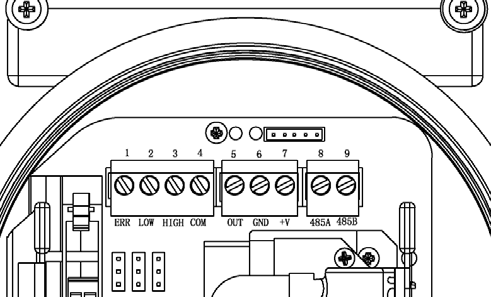
3. How are the terminals defined?
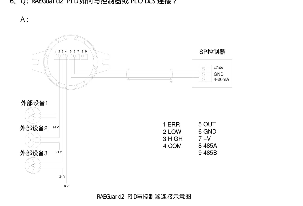
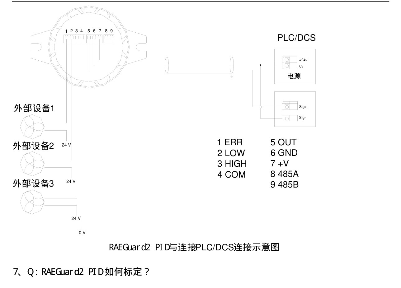
Nine terminals in three groups: 1–4 fault / low / high / common (ERR, LOW, HIGH, COM); 5–7 4–20 mA, 0 V and +V (OUT, GND, +V); 8–9 RS-485 A/B.
ERR LOW HIGH COM · OUT GND +V · 485A 485B
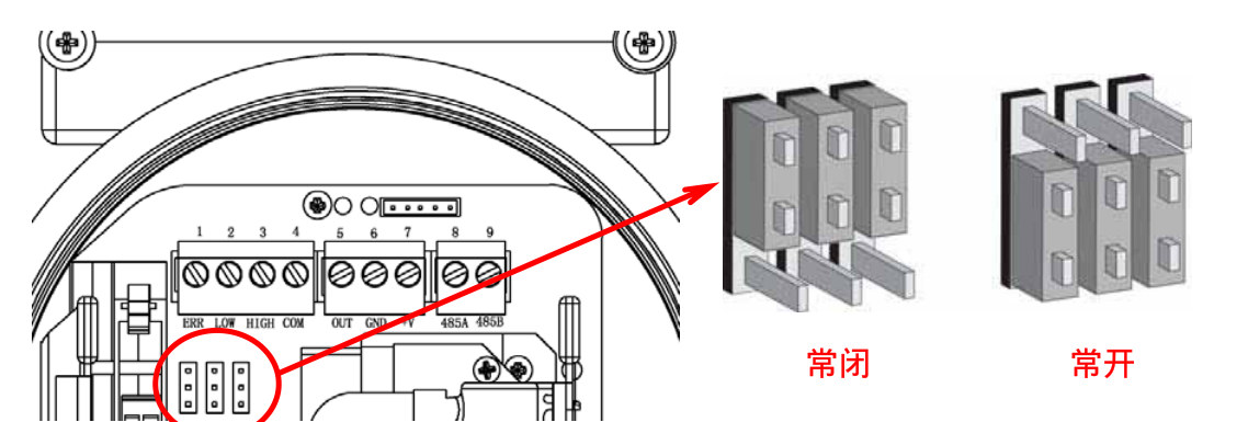
4. How do I set relay NO / NC?
After opening the lid, three 3-pin jumpers sit under terminals 1–3. Cap on the bottom two pins = NC; cap on the top two pins = NO. Check the figure before applying power.
Bottom pair NC, top pair NO
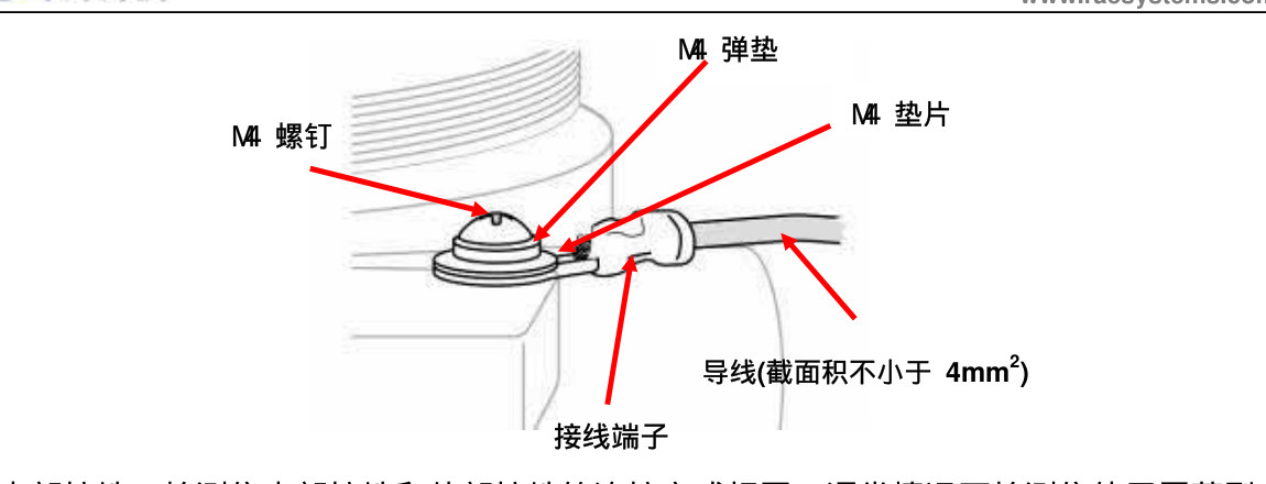
5. How should the detector be earthed?
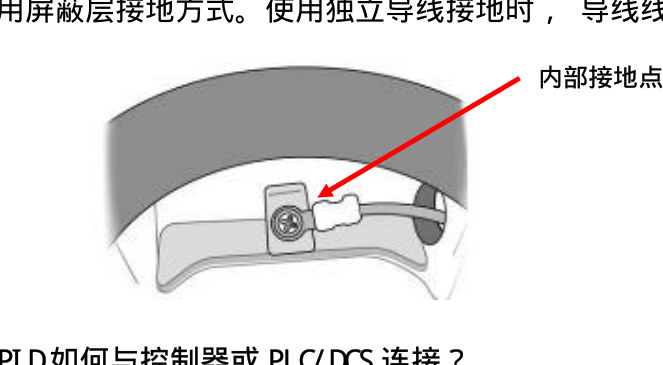
External: one end on the housing earth stud, the other to a reliable earth. Conductor ≥ 4 mm², earth resistance under 4 Ω. Internal earth uses the same stack. Shielded cable is typical — land the shield on the internal earth point. A separate earth wire must not be thinner than the supply conductors.
M4 screw / spring washer / washer, ≥ 4 mm²Land the shield on the internal earth
6. How do I connect a controller or PLC/DCS?
Three-wire: +V to 24 V, GND to 0 V, OUT to the 4–20 mA input. High / low / fault relays switch external loads via COM. RS-485 A/B for Modbus. On a PLC/DCS, OUT/GND are the signal pair and +V/GND are the supply.
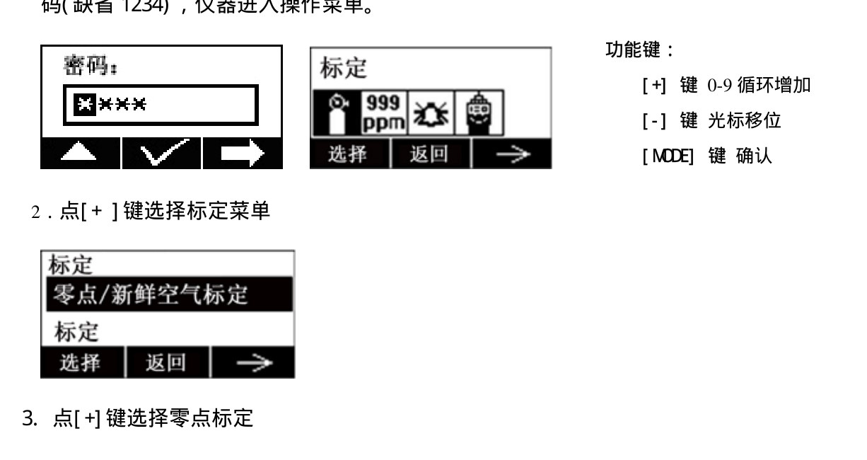
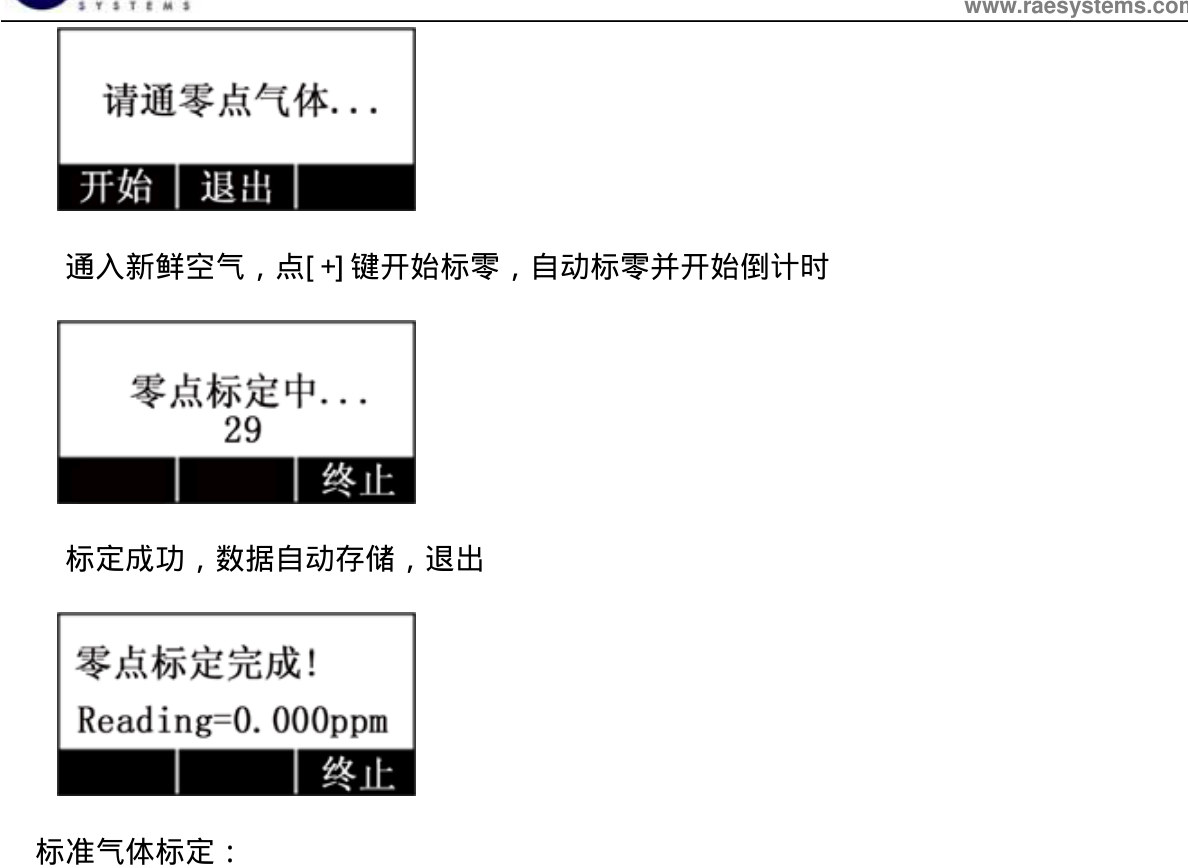
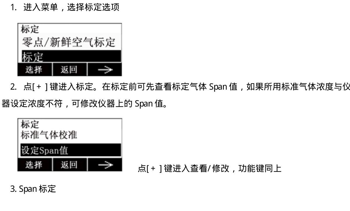
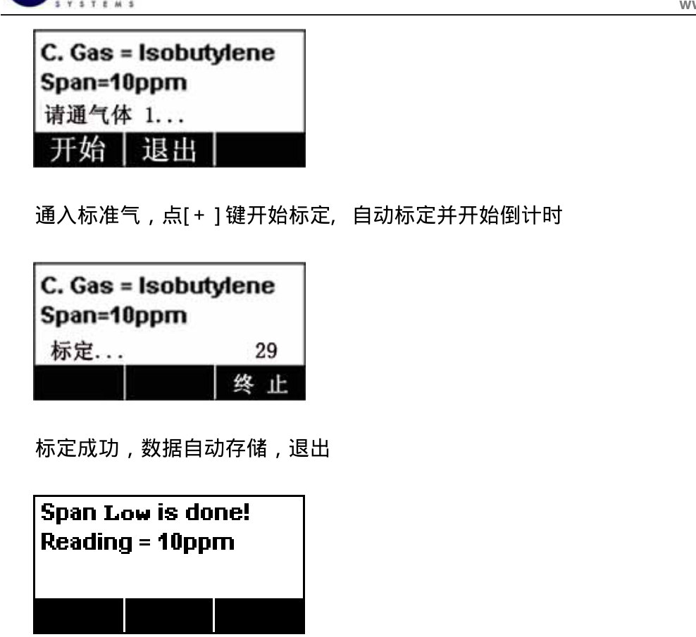
Tap [+], [−], [MODE] with the wand to open the password screen (default 1234: [+] 0–9, [−] cursor, [MODE] enter). Open Calibration: apply fresh air for zero (countdown then auto-store); then span — check or edit Span, apply isobutylene, press [+] to start. Close the cylinder and remove it when done.
Default password 1234Fresh air, countdown, auto-storeEdit Span if the cylinder differsIsobutylene example, Span=10 ppm
9. Which certificates exist, and where can I get them?
The specification lists ATEX, IECEx, UL/CSA and China Ex. Ask us for the files — do not use internal file-server paths.
10. Reading high with no TVOC present?
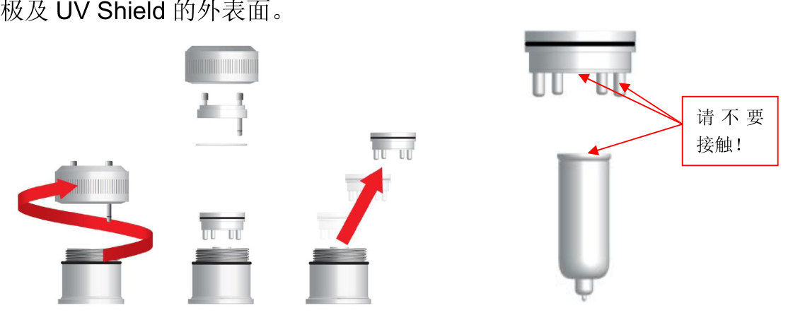
The detector electrodes or UV lamp are contaminated. Unscrew only the sensor cap, clean electrodes, UV shield and lamp window with absolute-alcohol swabs. Replace the C01-3007-200 detector if it is corroded.
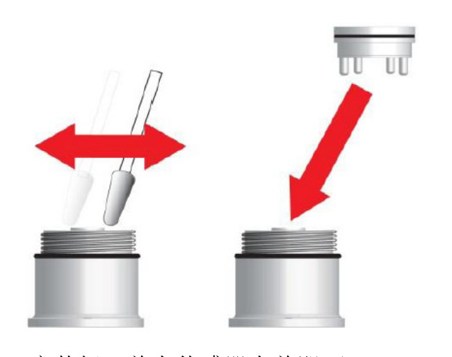
Do not touch electrodes, UV shield or lamp windowWipe the window, then refit the detector
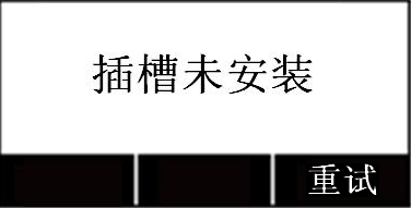
11. Display says “slot not installed”?
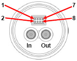
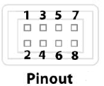
DigiPID or the D03-3003-000 safety barrier has failed. Measure pins 1 and 6 on the barrier: ~5 V means the barrier is good — reseat DigiPID, then replace DigiPID if the fault remains. No 5 V: replace the barrier.
“Slot not installed” / RetryIn / Out portsBarrier pins 1 and 6 ≈ 5 V
12. Over-range, red LED 3 flashes/s?
Contamination, condensate or heavy organics on the detector or lamp. At over-range the detector usually will not wash clean — replace it (C01-3007-200), or at least the UV shield.
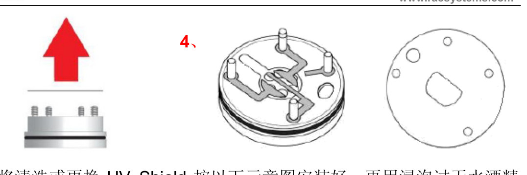
Split the housing, then lift the shieldReplace a thinned or missing shield
13. Sample-pump fault, yellow LED 1 flash/s?
Blocked path or a dead pump. Acid/alkali often plugs the sinter screw, or the internal inlet hose is pinched. Replace a stopped pump (D03-3002-000); if it still runs, clean the dust disc and sinter screws and unkink the hose.
14. Lamp fault, yellow LED 1 flash/s?
UV lamp dirty or dead. Clean the window as below; if it will not come clean, fit the OEM 10.6 eV lamp 050-0061-001. Do not wash the lamp with water; dry fully before refit.
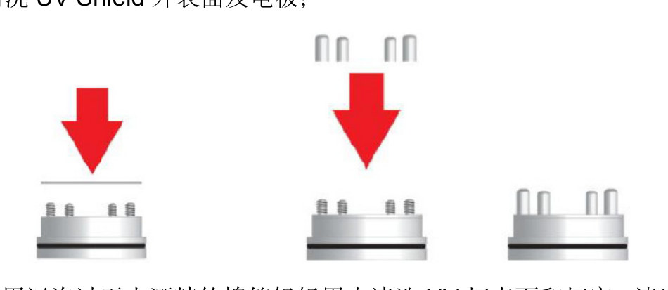
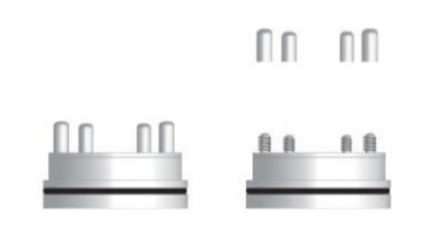
Absolute alcohol only — no waterSeat the shield, then the four caps
15. Negative sensor drift, yellow LED 1 flash/s?
Zero was taken on air that already contained detectable vapour. Repeat zero on fresh air or nitrogen.
16. Calibration error, yellow LED 1 flash/s?
Zero or span was wrong. Repeat two-point calibration: zero first, then a known span gas (isobutylene recommended).
17. Humidity-sensor fault?
The humidity sensor has failed and must be replaced.
18. Detector reading differs from the controller?
Small offset: recailbrate the controller. Large offset: disconnect the controller input and check 4–20 mA with a meter against the display, then decide host vs controller.
19. Reading keeps climbing when gas is applied?
UV lamp or detector is contaminated. Clean electrodes, UV shield and lamp window; replace if they will not come clean.
Do not touch electrodes, UV shield or lamp windowWipe the window, then refit the detector
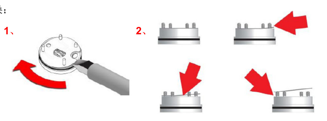
DigiPID cap service sequence
Use this for high zero, over-range, lamp fault and a climbing reading. Detector spare C01-3007-200 (includes 3 UV shields); lamp 050-0061-001.
1. Cap onlyUnscrew the sensor cap and lift the detector. Do not touch the lamp window, electrodes or the outside of the UV shield.2. Four electrode legsFlip the detector and unscrew the four electrode caps counter-clockwise.3. UV shieldLift the UV shield off. Clean electrodes with absolute-alcohol swabs; replace a corroded detector. Clean the shield inner face; replace it if the mask is thin or missing.4. Refit the shieldFit the cleaned or new shield, press the four electrode caps back, then wipe the outer face and electrodes with alcohol.5. Lamp windowGently clean the lamp window and chamber with alcohol. Inspect in light from several angles. No water. Dry fully.6. Refit the capRefit the detector and screw the sensor cap on. On site service the cap only — do not unscrew the whole DigiPID from the host.